Phono stylus rake and (cantilever) vertical tracking anglesfrequency responseSampling shorter sections of record grooves will recover more high frequency information.Sections sampled are shorter by elliptical AKA biradial than conical AKA spherical styli. To reduce wear and pressure, micro-ridge styli elongate contact area along an axis nearly normal to disc plane and groove direction. The nearly arises because records are cut with on average 92 (rather than 90) degree stylus rake angle. To maintain effectively shortest sampling sections, micro-ridge styli should be aligned to match record lathe cutters. alignmentPractically, few audiophiles have access to equipment for precisely measuring so-called rake angle of a micro-ridge stylus.Some users may measure stylus shank angle and suppose that working stylus shapes are ground with ridges parallel to shanks, despite no known (to me) documentation from manufacturers explicitly supporting that supposition. However, (cantilever) vertical tracking angles are commonly specified and relatively easy to measure. In theory, styli can be aligned by adjusting for strongest signal response to high frequency groove modulations. Using a personal computer, free software and audio interface, many users could also in theory make such high frequency response measurements.
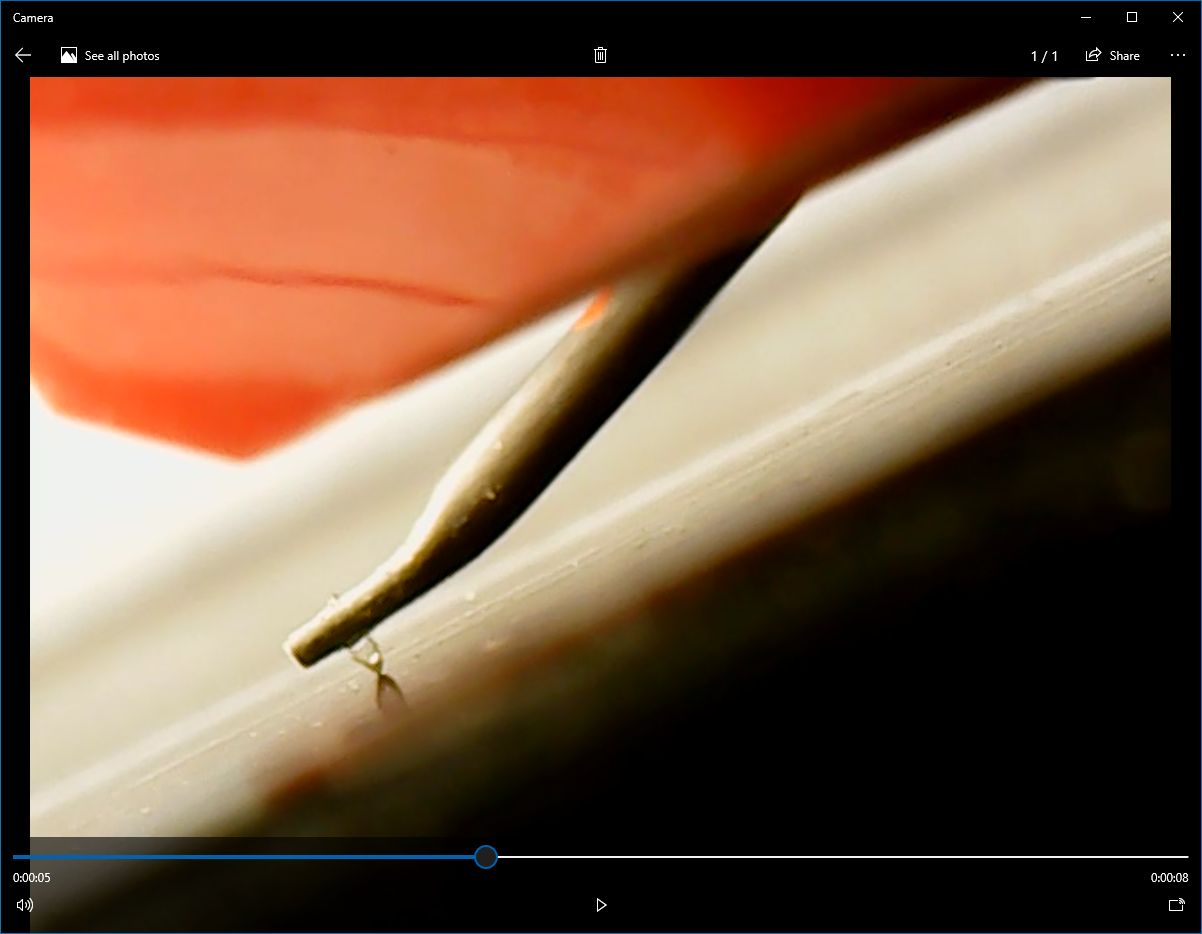
Practically, many turntables lack convenient adjustments for vertical tracking angles. Analog Planet and USB microscopesMichael Fremer's article motivated measuring stylus rake angle.Instead of his $249 Dino-Lite, I used a $25 generic USB microscope.
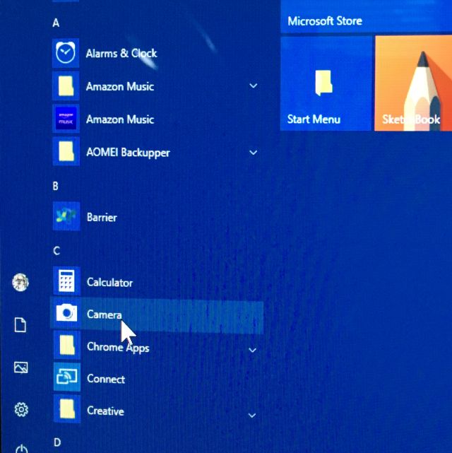
This device was plug and play on macOS High Sierra
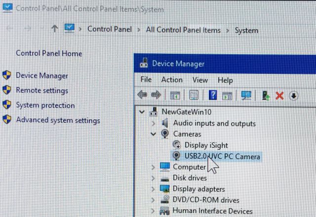
... but first required disabling a monitor's built-in camera:
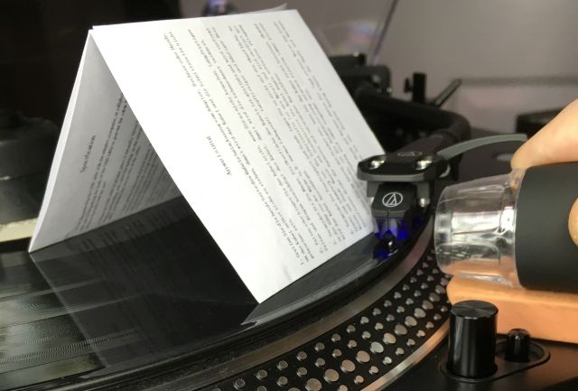
While Mr. Fremer invested in a better desk stand,
Instead of using the microscope's built-in light,
Instead of trying to capture a still image in focus,
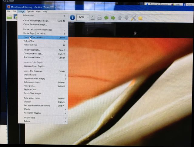
and pasted that into Irfanview,
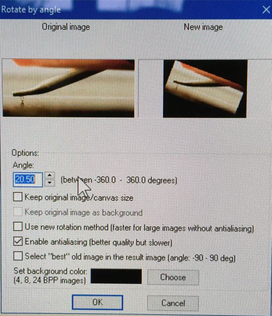
which is free and handy for this purpose because of an option to precisely rotate images.
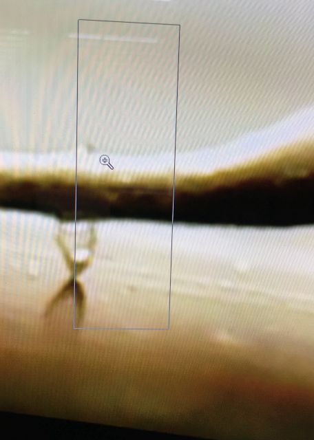
Dragging a mouse cursor over an image in Irfanview generates a box for cropping
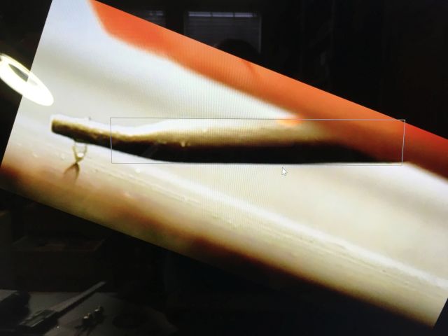
A first rotation makes the record surface horizontal.
With AT-LP140ZP tonearm base cranked all the way down,
A-T VM95ML microline is visibly uncentered in stylus shank; USB microscope standThis USB microscope became easier to use with a focus rack from a stand hung from a dial indicator magnetic base: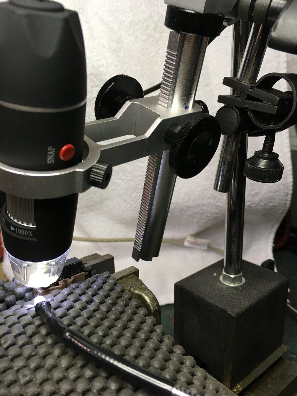
|
|
maintained by blekenbleu |