updated 8 Sep 2023
Arduino for STM32 Black ‘n Blue Pills, ESP32-S2,3
Background
I first used Arduino Blue Pills with SimHub’s Custom Serial devices plugin.
While highly useful, that plugin IMO has limitations:
- SimHub Javascript is relatively inefficient, hard to debug and maintain.
- Serial data can use only 7 bits per byte
- Custom serial plugin can log but not process received serial messages.
(Fake8 addresses those limitations.)
Arduino originally employed Atmel microcontrollers lacking native USB support.
Their workaround involves boards with USB-to-serial converter chips,
usually configured as USB COM (CDC) devices for serial IO,
which microcontrollers traditionally support.
Arduino IDE also works for ESP8266, ESP32 and STM32 microcontrollers.
WeMos D1 UNO R1 ESP8266 board communicates via CH340 USB-to-serial chip.
Note that there are now fake CH340 chips
which require an older Windows driver.
STM32duino: who’s on first?
- History
- originally by Leaflabs for Maple, then Roger Clark for STM32F1/F4
- “Official” STMicrosystems
stm32duinosupports many STM32 chips and boardsstm32duinosince core release 2.8.0, supports only Arduino IDE 2- I used Arduino 1.8 for Blue Pill, then Arduino 2.3.6 for Black Pill
Blue Pill
Unlike Black Pill’s OTG USB, Blue Pills support 8 endpoints, thus composite USB devices.
Many STM32 chips’ hardware and ROM bootloaders support (DFU) USB directly,
but Blue Pill’s chip lacks ROM USB bootloader support.
STM32F103C chips officially have 64K flash, but
many have 128K.
There are at least 4 ways to flash STM32 chips:
1) SWD via ST-LINK
Use this to install an HID bootloader on Blue Pills
Unlike Black Pills, new Blue Pills lack a ROM USB bootloader.
2) (Arduino) USB bootloader[s] <- there have been several:
- STM32duino Bootloader
AKA bootloader 2.0 AKA HID bootloader
For downloading Blue Pill sketches using ST Microelectronics-supported libraries
USB bootloader in Blue Pill flash reduces storage available for Arduino sketches. - other bootloaders are IMO obsolete:
- Maple-derivative bootloaders
- Maple boards had USB reset hardware to force re-enumeration
- Roger Clark’s 8k bootloader
Be aware that some of Roger Clark core code is also called Stm32duino.. - Not sure which core (libmaple or stm32duino) this bootloader supports, but is 4k
3) STM serial bootloader - tedious for frequent reprogramming
Blue Pills have only a serial bootloader in ROM; a USB bootloader gets installed in flash.
Load firmware via USART1 by first jumpering:
Boot0 HIGH
Boot1 LOW
… then resetting MCU
4) DFU (device firmware update) using DfuSe utility, e.g. for Black Pills
using its STM32 system memory bootloader in ROM,
but, again USB is NOT supported by Blue Pill’s ROM bootloader.
STM32duino for Blue Pill expects a USB HID bootloader,
which gets launched by Blue Pill’s ROM bootloader,
then Arduino uses that USB HID bootloader to install sketches above it in flash.
A clone ST-LINK V2 costs no more than a USB COM dongle,
connects to dedicated SWD pins on e.g. Black or Blue Pills for code load and debug.
Clone USB COM dongles may not support 3.3V to Blue Pill serial boot pins..
Blue Pill boot jumpers need not be changed when flashing by ST-LINK or HID bootloader.
STM32duino
Although many STM32 Arduino projects still use Roger Clark’s core and bootloader (AKA Maple),
Arduino now gets an ST Microelectronics-supported core and board manager
for which Blue Pill gets an HID bootloader,
as described on YouTube.
That video installs the Blue Pill HID bootloader via USB COM dongle,
but we here use an ST-LINK V2 clone.
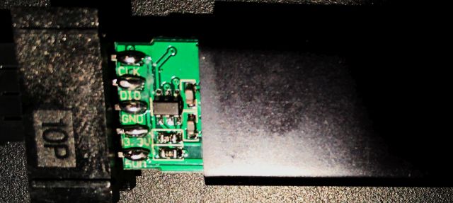
My clone ST-Link happens to have the correct pinout printed on its cover;
Verify ST-LINK clone pin artwork; slide cover partly open (along the USB plug):
Here is the Arduino for STM32 forum. It mostly replaced older Maple.
Here is the Arduino software page. Use Legacy IDE (Arduino 1.8.X) for portability.
- Arduino IDE 2 version and STM32 core 2.8.x. support debugging,
but NOT portability…- switching Arduino 2 between ESP32 and STM32 requires hacking each time
C:\Users\%username%\arduino\arduino-cli-yaml - Instead, continue using portable Arduino 1.8 for ESP32…
- switching Arduino 2 between ESP32 and STM32 requires hacking each time
Blue Pill SWD pins for ST-LINK
This video programs a Blue Pill using STM32 ST-LINK utility.
Wiring Blue Pill to ST-LINK V2 clone:

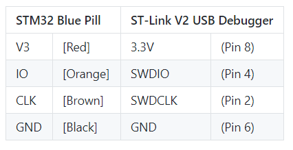
Connect 3.3V from ST-LINK to Blue Pill
- only when Blue Pill has no other connections.
Put another way, when using ST-LINK to debug Blue Pill e.g. plugged to USB,
do NOT connect 3.3V to Blue Pill from ST-LINK.
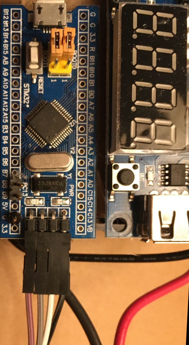
Here is my ST-LINK connected to my harness tensioning Blue Pill:
Installing (by Windows ST-LINK) Blue Pill HID bootloader for STM core
- For Windows, stlink-org tools depend on STM’s
ST-LINK driver,
bundled with STM32 ST-LINK utility,
which utility was also wanted for updating clone ST-LINK firmware. - Also use STM32 ST-LINK utility to install HID bootloader.
These instructions apply specifically for 64-bit Windows, ST-LINK clone,
HID-bootloader, Blue Pill and STM core.
1) Download and install STM32 ST-LINK utility
in my case, to D:\packages\STM32\
2) Plug bare ST-LINK clone into USB.
If it shows up in Device Manager under Other devices (with a yellow warning),
then drivers were not installed; see 1)
else it should appear under Universal Serial Bus Devices.
3) Launch STM32 ST-LINK Utility.exe
in my case,
D:\packages\STM32\ST-LINK Utility\STM32 ST-LINK Utility.exe
4) Select ST-LINK > Firmware update
click Device Connect
click Yes>>>>
5) Unplug ST-LINK clone from USB and wire it to Blue Pill as shown above.
6) Connect Blue Pill BOOT-0 and BOOT-1 pins (or on-board jumpers) to 0
** and leave them! **
Disconnect everything except ST-LINK from Blue Pill, and plug ST-LINK to USB.
7) Download stm32_binaries.zip from the latest HID Bootloader release
From it, extract: hid_generic_pc13.bin
(Blue Pill on-board LED is connected to pin PC13)
in my case, to D:\packages\STM32\
8) To flash HID Bootloader to a Blue Pill, in STM32 ST-LINK Utility:
File > Open File... > hid_generic_pc13.bin
Target > Erase Chip
Target > Program... > Start address 0x8000000
File path D:\packages\STM32\hid_generic_pc13.bin
click Start (that should complete quickly)
(Blue Pill red LED on for power, green LED flickers quickly)
Unplug ST-LINK, unwire ST_LINK from Blue Pill, and connect Blue Pill to USB.
(Blue Pill red LED on for power, green LED flickers quickly)
Note A bad Arduino sketch download can leave a Blue Pill unable to be recognized by Windows,
and reflashing the HID Bootloader without wiping the bad sketch by erase chip may not recover it.
Troubleshooting
- Does a downloaded sketch otherwise appear to work (e.g. blinking LED),
but not respond to Arduino?
If so, then perhaps that sketch is not correctly opening a Serial connection.
Otherwise, it may be trying to use inappropriate pins
or a wrong board definition - If ANY simple sketch downloads and still is recognized by Arduino,
then you very likely use the correct board definition. - Does the blink sketch actually blink the LED as expected?
If not, something similar happened to me when compiling and loading a sketch
with an incorrect board selected.
To check whether the correct board is selected,
build and load an example sketch
specific to the selected board:
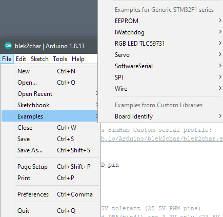
File -> Examples -> (examples for selected board type):
- If ANY sketch works for you, then problematic sketches may use pin[s]
that Arduino (or the board) expects to use for communication and control.
It is important to locate, if possible, an diagram showing
how the board support package assigns pins on your specific module for Arduino. - Another possiblity is that your sketch enables pins in some way
that causes the STM32 processor to lock up or be too busy to respond to Arduino.
Debugging that might require
moving suspect pin initializations from setup() to some separate routine
that gets called only after the sketch receives input from e.g. Serial Monitor. - Another trick for Arduino to work with downloaded sketches:
those sketches SHOULD correctly open communications as Arduino expects,
even if sketch function does not otherwise need it.
Making this initial message unique confirms which sketch is loaded.
For Blue Pill, that amounts to having, in setup(), something like:// Initialize serial and wait for port to be opened: Serial.begin(115200); while (!Serial) delay(1); // wait for native USB serial port to connect Serial.write("Blue Pill HEX_echo sketch has connected. "); - Genuine original STM Blue Pill modules are basically no longer available,
and you probably have some similar but perhaps incompatible clone board.
That clone may need a different board profile…
Installing STM32duino support
Since SimHub already includes an older version of Arduino,
install another portable (ZIP file) instance for STM32;
no need to install Arduino-specific driver[s]…
1) Download, unzip, and run Arduino
in my case, to E:\my\Arduino\
much of the following is thanks to sgbotic
2) Go to File > Preferences, add to Additional Board Manager URLs text box:
https://github.com/stm32duino/BoardManagerFiles/raw/main/package_stmicroelectronics_index.json
3) Go to Tools > Board > Boards Manager, enter search for STM32:
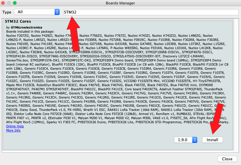
8 Sep 2023: Latest version is 2.6.0;
click STM32 Cores, then Install (takes quite awhile)
4) Quit and restart Arduino; then
from Tools > Board: > STM32 Boards, select [Generic STM32F1 series].
From Tools > Board Part Number:, select [BluePill F103C8].
see note above, in last bullet under Troubleshooting, about clone boards.
From Tools > Upload method:, select [HID Bootloader 2.1] or newer.
Be sure to check Tools settings before Sketch upload; Arduino seemingly likes to change them,
then Blue Pill will not be a recognized device after uploads.
Check in Windows’ Device Manager under Ports (COM & LPT) for USB Serial Device (COM*n*),
where in my case n = 3,5 or 10.
Port: COM[5] is unavailable until a sketch is loaded, e.g. Blue_Blink:
Blue Pill pinout
- 5V tolerant PWM wanted for driving hobby servos, e.g.
PA8-10andPB6-9. PA3, PA2RX2, TX2 work also for Black PillHardwareSerial- 5V tolerant CAN BUS pins
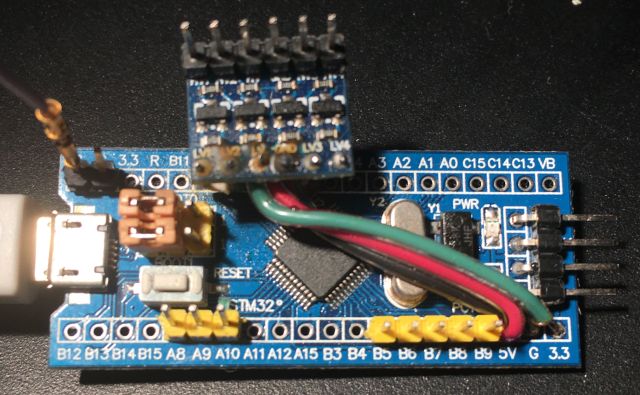
PB8,9work for me. - In addition to seven 5V tolerant PWM pins, up to 7 more can be available by level-shifting:
To drive automobile dash instruments by Blue Pill from SimHub, go here
A simple next step adds servos to the blink loop sketch.
This servo cycling sketch is under GitHub revision control,
with a shortcut to that sketch folder in the Arduino “work” folder.
Both of these ploys work; the sketch runs..
This sketch can be used to verify servo wiring to a Blue Pill without serial control.
USB Serial servos e.g. for SimHub harness tensioning
Here is the Arduino reference for Serial communication
In STM32duino, Serial device is USB virtual COM port,
using PA11+12, and Serial1 is UART PA9+10,
but Serial may be UART in PlatformIO Arduino framework
unless configured as a USB Virtual COM port in Tools.
Put while (!Serial){;} in setup(){}
Toggling LED off before and on or blinking after provides connection feedback.
The first Arduino sketch I found that combined Serial and <Servo.h> is
Matt Williamson’s serial_servo_rx.ino
USB Serial protocols
In theory, USB communication should be quite robust,
using shielded balanced pairs for signals and USB device transceivers powered by their host.
In practice, most USB devices have one side of tranceiver signal pairs tied to their power ground,
so unbalanced and liable to EMC and ground bounce issues.
USB device communication is in units of 8-bit bytes,
but SimHub Custom Serial devices are constrained to use only 7 bits of each byte.
While each single USB bytes may be relatively robust to electrical interference,
longer messages become increasingly vulnerable to failure.
Consequently, keeping messages short and providing for recovery (or at least resynchronization) are concerns.
First generation single-character control avoids serial string blocking and overflows.
Useful rotation range for my harness’ servos is less than 127 degrees;
direct odd rotation values 3-127 to the right harness strap
and even rotation values 2-126 to the left,
reserving values 0-1 to set strap offsets based on immediately next values.
Green LED blink codes feedback when processing servo values,
with 50% duty cycle for idle operation.
Perhaps better to use that LED to signal when servo values are max..?
Blink timing by delay() impacts serial bandwidth, so use millis().
For serial servo control, with or even without SimHub Custom serial device,
this Blue ASCII Servo sketch accepts e.g. ASCII characters from Arduino Tools > Serial Monitor.
to move left or right servo based on least-significant bit.
See STM32duino (above) for Blue Pill flash programming information.
Characters > 127 do not arrive intact from SimHub JavaScript,
but useful strap servo range is < 127, with offsets applied to received values.
Testing suggests that, running on STM32 Blue Pill,
this sketch handles 60Hz updates of 4 characters, where 2 should suffice.
By changing from Blue Pill-specific PWM pin and LED assignments,
this sketch should work for other Arduino-supported modules with PWM-capable pins.
Corresponding SimHub Custom serial hacking is described here.
Handle serial input by callback
Blue Pill firmware generations
- As described above, first generation use the least signficant bit of each USB byte
to e.g. select left or right harness tensioning servo.. - Since serial communication between SimHub and USB devices is inherently asynchronous,
some mechanism is wanted for sorting multi-byte message starts and/or ends. - A second generation allocates 3 msb for PWM pin selection,
with 0x70 reserved for special commands e.g. 0x7F for servo LUT loading,
leaving 4 lsb to index into a 16-entry LUT of PWM values.
This intends to cram so much control as possible into single 7-bit characters. - A third generation pairs 7-bit ASCII characters (14 bits),
where the most significant bit in each 7-bit character
identifies it as first (1) or second (0) character of a pair, leaving 6 bits for commands and data.
The next bit in the first character is most significant of 7 channel data value bits,
while the 5 lsb index a channel, which may e.g. be a PWM pin.
The largest 5-bit channel index is reserved for special commands.
Available 6 lsb of second characters are 6 lsb of channel data values. - Fourth generation protocol uses 8 bits:
AFake8.shsdsSimHub Custom Serial device plugin profile communicates with another SimHub Fake8 plugin
that converts Custom Serial device 7-bit data to 8-bit sequences for e.g. Arduino PWM sketches.
SimHub plugins are implicitly synchronized by SimHub’s (60Hz) refresh rate,
simplifying serial communication between them.
PWM fan
ESP32 MIDI seemingly doomed…
STM32 MIDI